I took home with me the same board that I made previously So I already had an input on a board I designed, so I only needed to program it. In order to do that, I took the C code from the hello echo example, and modified it to the hello button example.
On the Attiny 45, the button is on pin 3 which is the pin at port B, pin 4 it's pin PB4. So what I can deduce to my Attiny 44 board, is to giure out where to connect my button, whichin my case was pin 10 or pin PA3.
I also had to find on the datasheet that the serial on the 45 board was pin PB2, and on my 44 board it would be PA1. I had to check that they were compatible.
It took me a while to figure it out, but I finally got it. I had to go to the datasheet of the 44 chip and check the pins port addresses, and change the C code. I had to check which pins the button was connected on the 45 program, and which pin mine was connected to. I also had to go to both IC's datasheets and check that they both were I/O with the same functionality. They were. On the original code, the button was connected to pin PB4 and on mine, it was to PA3. The serial output was also different, but I followed the same process. This is the original hello button statements I changed:
                  #define bit_delay_time 102 // bit delay for 9600 with overhead
                  #define bit_delay() _delay_us(bit_delay_time) // RS232 bit delay
                  #define half_bit_delay() _delay_us(bit_delay_time/2) // RS232 half bit delay

                  #define input_port PORTB
                  #define input_direction DDRB
                  #define input_pin (1 << PB4)
                  #define input_pins PINB
                  #define serial_port PORTB
                  #define serial_direction DDRB
                  #define serial_pin_out (1 << PB2)
I changed them to this:
                  #define bit_delay_time 8.5 //changedd to 115200 with overhead as in the Attiny44 example (we have the resonator).
                  #define bit_delay() _delay_us(bit_delay_time) // RS232 bit delay
                  #define half_bit_delay() _delay_us(bit_delay_time/2) // RS232 half bit delay

                  #define input_port PORTA //input pin from button is PA3
                  #define input_direction DDRA //we're using the A port pins
                  #define input_pin (1 << PA3) //change the input port
                  #define input_pins PINA //serial will also use port A
                  #define serial_port PORTA
                  #define serial_direction DDRA
                  #define serial_pin_out (1 << PA1) //serial FTDI is connected to PA1
After this, I had to change the heading of the makefile to this:
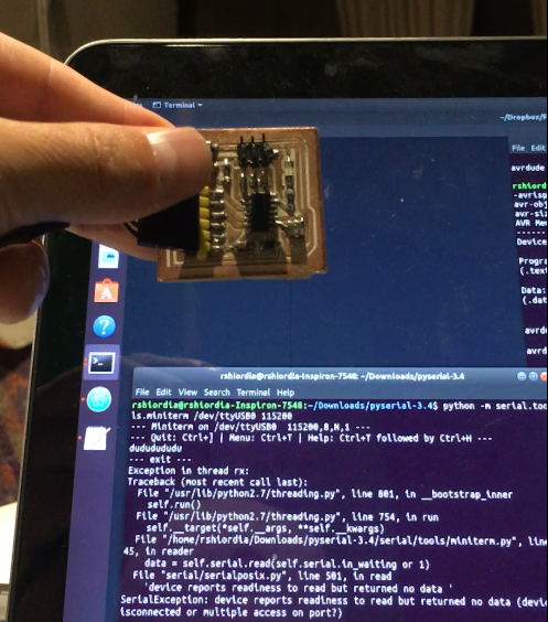
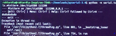
Overall it worked for like 10 seconds, and sadly, I didn't get the video for the "d" and "u" characters on the terminal. I was very satisfied when I saw those little letters, but the serial communication broke down after the first couple of tries. Other programs like the blinking program work, so my guess is that the problem lies in a short circuit on the serial communication pins. This is because I uploaded the hello echo program, and the return is gibberish. That means I know that the chip is being programmed, I know that the output pins are working and that the button is also working.
Here you can see the board returning the "d" and "u" characters to the serial port!
After this initial test, something broke down, and it stopped working. I later realized that the board had some connections come loose.
Programming
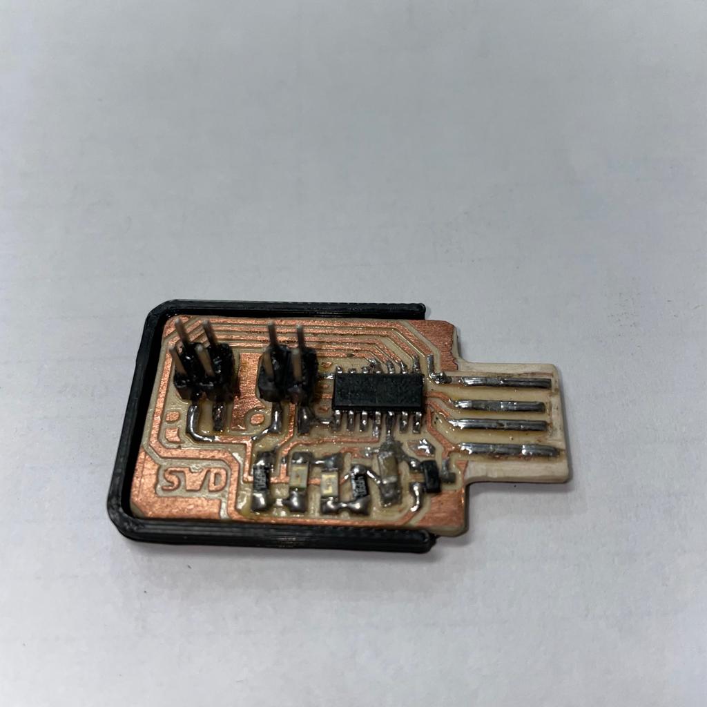
To program the board you first need a programmer that we made before. That programmer has a target board connection, which we will use ONLY ONCE to upload the Arduino Bootloader.
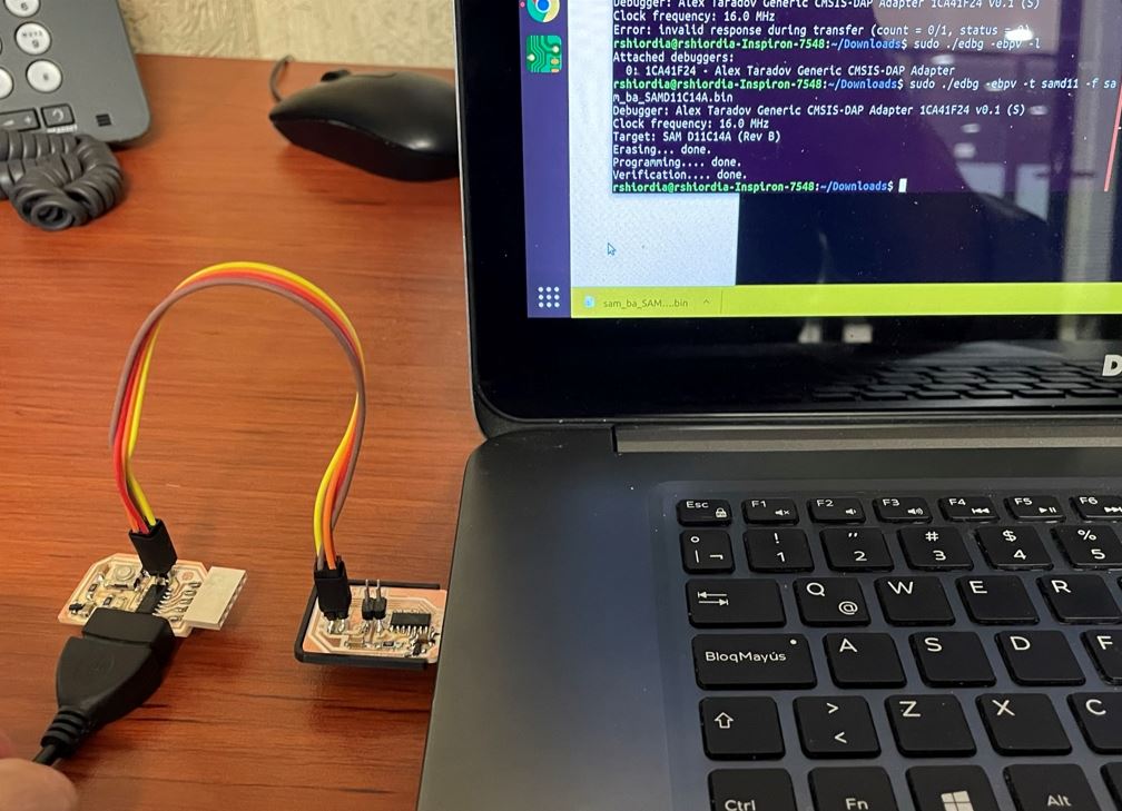
First, connect everything like so:
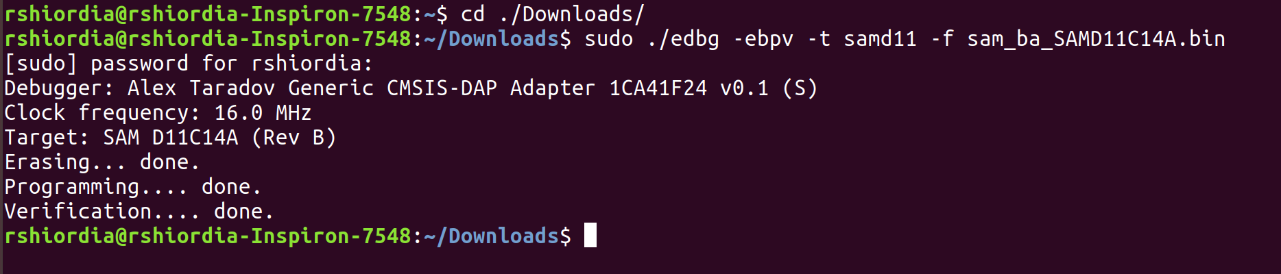
Then, download the arduino bootloader from Quentin Bolsee .
Put the file in the same folder as EDBG and run:
edbg -ebpv -t samd11 -f sam_ba_SAMD11C14A.bin
Once that is done, you will be able to program your board directly from Arduino. Here are the steps:
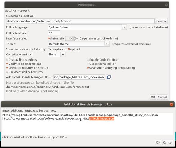
first, go to file>>> preferences and add the URL for the arduino core that will allow us to select this chip and program it from the Arduino IDE. The URL is this one:
Then, you should add the SAM D|L|C core for Arduino using tools>>board>>>>>boards manager... type generic d11 on the search bar and it should appear. It won't appear unless you add the URL from last step.
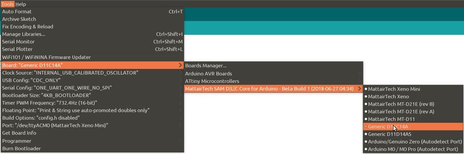
Then and only then will you be able to select the board from the tools menu:
Finally... you can now upload code to the board using normal arduino In my case, the first code I uploaded was this:
So I wanted to create a little bit more complex behavior than a blinking LED.
What I thought, was to create a PWM signal to control the LED.
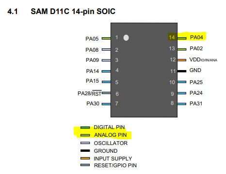
First off, I have to check the datasheet to see if the pin that I have my LED supports that behaviour.
I have my LED connected on pin PA04 which is compatible with analog signals.
This is the first version of the code, just to check if everything is working.
I will be using analogWrite() which creates a variable duty cycle signal depending on the value you feed into it. This signal goes from HIGH to LOW depending on afrequency, and that "simulates" a variable voltage.
After that, I made adjustments to dynamically change the value on the analogWrite() function.
I created a variable called "val" that starts at 0. This will be the value sent to the analogWrite() function.
Then I created a value called "d" that will control delay.
Then on the loop section I only fed the "val" variable to the analogWrite function and increased that same variable by 1 using val++;
After that, using a conditional statement, I reset the "val" variable to 0 if it's over 255, because the analogWrite() function takes a value between 0 and 255. delay(d) just manages the frequency of the update. Larger valuse will make the LED "breathe" slower or faster.
                   int ledPin = 4;
                   int val=0;
                   int d=10;
                   void setup() {
                     pinMode(ledPin, OUTPUT);
                   }
                   void loop() {
                       analogWrite(ledPin,val);
                       val++;
                       if (val>255){
                         val=0;
                       }
                       delay(d);
                   }
This is a video of how it looks. You'll notice that it "breathes" but it does so not how I wanted. I wanted it to go form 0 brightness smoothly up to the max, and then smoothly back to 0.
However, it's getting up to the max brigthness, but then it abruptly goues back to 0.
This is not that hard to correct. What I then did, was to basically create a new variable, which is the incement at which it increases. Instead of turning "val" back to 0, I'm going to just change the sign of this "increment".
This is the new code:
                     int ledPin = 4;
                     int val = 0;
                     int d = 5;
                     int increment = 1;
                     void setup() {
                       pinMode(ledPin, OUTPUT);
                     }
                     void loop() {
                       analogWrite(ledPin, val);
                       val += increment;
                       if (val >= 150) {
                         increment *= -1;
                         delay(500);
                       }
                       else if (val <= 0) {
                         increment *= -1;
                         delay(500);
                       }
                       delay(d);
                     }
This is a video of the new behaviour which you'll see that behaves like I wanted it to.
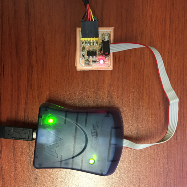
Programming using AVRISP
The setup
I used my ATtiny board that has a button and an LED. The LED is connected to pin 6 of the IC and the button is connected to pin 10.
One of the most important things is to also provide power to the ATtiny44 using the FTDI interface by plugging that one to anothe USB port.
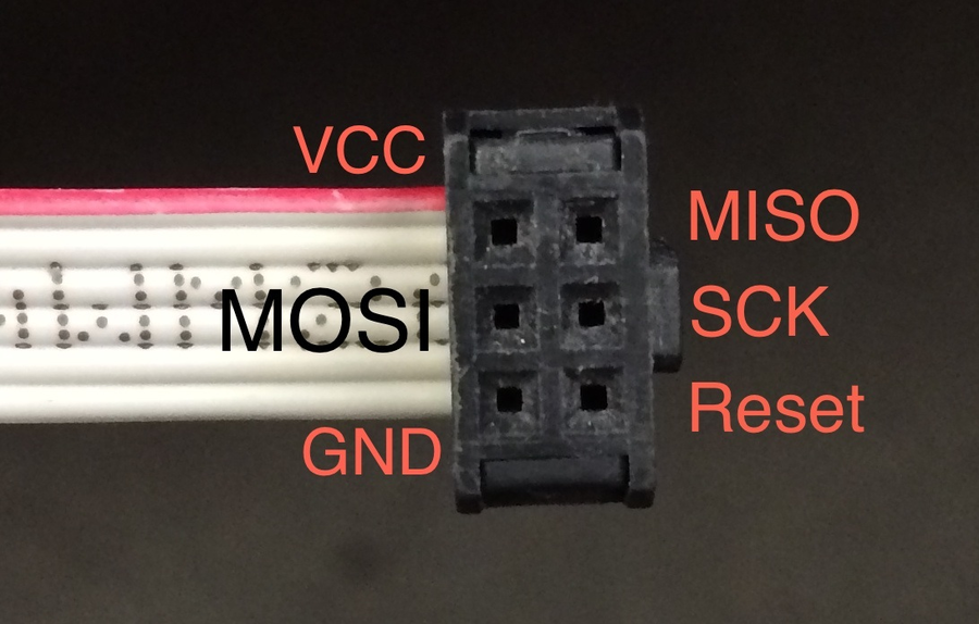
One of the first hurdles is figuring out how to connect the AVRISP mkii to the ICSP port of my board. Remember that these pins are the MOSI, MISO, RST, SCK, VCC, GND
We know from the assignment in week 5 that the VCC pin connects to pin 1 on the ATtiny44 so with that information, on the cable, we need to find the VCC. I surmised that the red cable on the connector had to be a clue: The The red cable is VCC!
Get and install AVRDUDE with LIBUSB and GCC compiler:
To use the AVRISP mkii you need to first install avrdude and the c compiler. This is important as the avrdude is the software that talks to the ATtiny using the USB serial port.
Once you connect the AVRISP then you can use lsusb to see if the computer is propperly reading it. Then install AVRDUDE with LIBC and GCC:
After this, then you can start to program the board. The first thing is to create the makefile. You have to download from here the echo program in c. You can do a nano hello.ftdi.44.echo.c to open a new file. Then paste the code there and do ctr + o to save without changing the name, and then ctrl + x to close the file.
Do the same for the make file here .
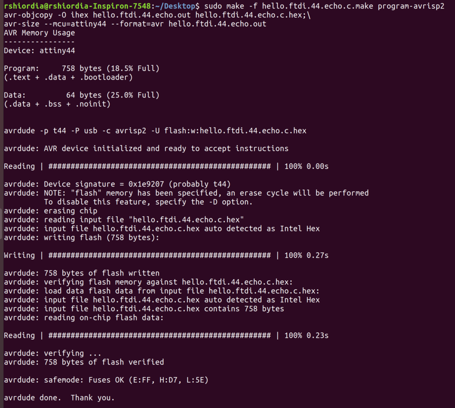
You will then send the file to the board using the code:
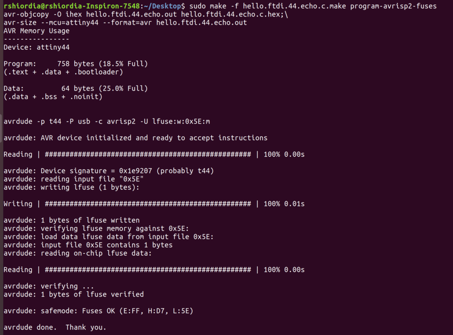
sudo make -f hello.ftdi.44.echo.c.make sudo make -f hello.ftdi.echo.44.c.make program-avrisp2-fuses sudo make -f hello.ftdi.echo.44.c.make program-avrisp2
It's important to note that the makefile references the c file, so the name of the file should be the same. Also, if you are using another programmer, the makefile has several options written there, so be sure to change the name of your program tot he device you are using. In my case I had to use the avrisp2 options which correspond to the AVRISP mkii programmer.
If everything goes well, you should see somehting like this.
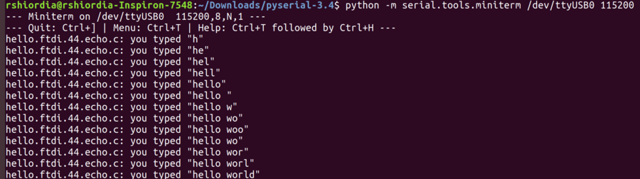
The C program writes back to the serial whatever characters you print to it. We need now to talk to the board. Plug the board using the FTDI interface directly to usb. You will need to find out your device name exactly. Type:
ls /dev/ttyUSB*
This will tell you the name of the device, which in my case was /dev/ttyUSB0 You will need this name to open the serrialport using pySerial.
To install pySerial use:
sudo apt install python-pip pip install pyserial
Download PySerial and go into the directory where you extracted. Then type:
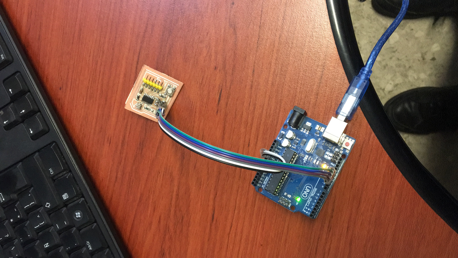
The first thing is to setup the Arduino to talk to the Attiny44. To do this follow the instruction on this page
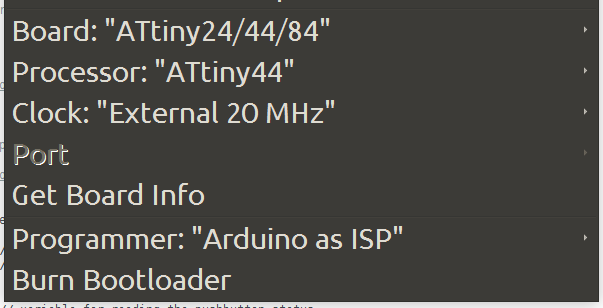
After that, you upload the ARduinoISP sketch to the Arduino normally. Then, connect the board and configure the ATtiny44 configuration. Set Board, Clock, and Programmer like this:
You can then load the button program from the examples but be sure to switch the pin numbers. in my case pins 3 and 7 even though the Attiny pins were 6 and 10. This has to do with the pin configurations and arduino cores. Here is the Arduino Sketch in action:
 Then, you should add the SAM D|L|C core for Arduino using
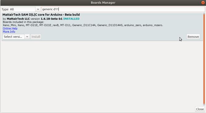
 You can then load the button program from the examples but be sure to switch the pin numbers. in my case pins 3 and 7 even though the Attiny pins were 6 and 10. This has to do with the pin configurations and arduino cores. Here is the Arduino Sketch in action: